

Understanding Radio Control Gear
Understanding the basics of radio control gear and how it makes your rc plane do what you want it to (most of the time!), is important if you want to get the most out of your new hobby.
Incidentally, this page was originally written before the advent of 2.4GHz (gigahertz) rc systems, so it mainly talks about the traditional MHz (megahertz) radio control gear. But with that said, the fundamental operating information outlined in this article covers both types.
The basic components of a typical radio control system are the transmitter, receiver and servos.
Battery packs, or individual cells, are needed to power all the components. However, receivers and servos of modern electric power (EP) rc airplanes don't usually have their own battery pack because their power is taken directly from the motor battery pack via what's known as a BEC - more on that later.
Traditional MHz radio control systems were commonly purchased as a complete set that included the transmitter, receiver, 4 standard servos and a battery charger. An example is shown below, in this case the Futaba T4YF, a popular rc system in its day.
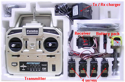
But these days it's more common to buy just the transmitter and receiver, or even just the transmitter alone, without any servos. This is simply because servo type and size varies so much these days, because their applications are far more varied than ever before, that it would be hard for the manufacturer to know which type of servo to put in the box. Far easier to leave the choice up to the pilot!
Number of Channels vs. Channel Number
In the radio control hobby the word channel, which you'll see a lot, has two completely different meanings. The first meaning is the number of channels that an rc system and airplane has, and in this case the word channel refers to each separate controllable function of the model.
A one-channel rc airplane has only one function that can be controlled by the pilot. For example rudder movement or electric motor on/off. Two channels could be rudder and motor while three channels could be motor, rudder and elevator (or motor, ailerons and elevator).
A typical 4-channel rc airplane will have motor, ailerons, elevator and rudder control; the four primary rc airplane controls.
There are no set rules as to how many channels an rc airplane can have, it is purely dependant on the plane itself and/or how many functions the pilot wants to control.
More complex models may require 6, 7, 8 or more channels to operate the primary controls plus any additional functions such as retractable landing gear, flaps, landing lights, sound effects, camera operation to name a few.
Channel Meaning #2
The second meaning is the channel number and this refers to the radio frequency channel on which the radio control gear operates.
Different countries have different frequency channels, legally designated for radio control flying, that fall within certain ranges of the MHz frequency band. The designated frequency channels are numbered and no two pilots can fly together on the same MHz channel at the same time, because one rc system would interfere with the other, causing serious control problems for both pilots!
Indeed, my very first radio control model, a 2-channel glider was 'shot down' on its maiden flight by a fellow flyer thoughtlessly turning on his same-frequency transmitter without checking which frequency I was on first!
It's worth noting at this point, though, that only MHz radio control gear uses designated frequency channels. The modern-day 2.4GHz radios don't use the same technology and so separate frequency channels are not necessary.
This is a huge advantage with 2.4GHz systems - you don't have to worry who else is flying, as there is no risk of unwanted radio interference from your fellow rc pilots.
Radio Control Gear Components
Let's now take a simplified look at each of the main components that your typical rc system consists of...
Transmitter ('Tx' or 'Tx')
The transmitter, commonly just called the radio, is the box that you hold and use to control your model.
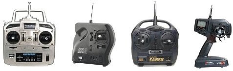
Several different configurations of rc transmitter exist, the common types are shown below and are, from left to right, traditional 4+ channel, single-stick 3-channel with slide motor control, two-stick 2-channel and a pistol grip 2-channel. The latter is used with radio controlled cars.
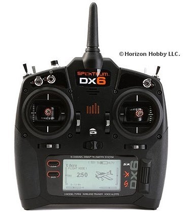
Above: a newer 2.4GHz transmitter, the popular Spektrum DX6.
For the purpose of this page we'll focus on a 2-stick multi-channel (4+) rc aircraft transmitter because that's the type you'll most likely use, be it a MHz or GHz one.
Such a Tx has two control sticks, trim buttons/sliders and various switches. There may also be rotating dials and/or sliding levers on the face and top of the transmitter, so as to be within easy fingertip reach. These are the auxiliary channels and can be used for functions on the aircraft over and above the four basic controls.
A MHz transmitter has a collapsible metal antenna, whilst a 2.4GHz Tx has a much shorter, non-collapsible one. The latest 2.4GHz transmitters commonly have an internal antenna, sometimes hidden in the carry handle.
The MHz antenna will extend to around 4 ft. in length, compared to the very short 2.4GHz one. This length difference is because 2.4GHz radio wavelengths are much shorter, so require a shorter antenna.
If your Tx is 'computerised', an LCD screen will display all the relevant information - programmed settings, menu options, battery voltage, timer etc.
If it's not computerised then there will be a simple battery voltage meter or indicator lights on the face of the Tx, and no LCD screen. Most transmitters these days are computer ones, and only the most basic are not.
The main features of a 6-channel MHz computer Tx are shown below:
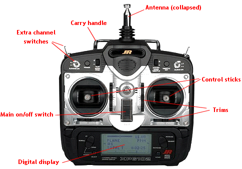
On a Tx like this both sticks move up & down and left & right to enable two functions to be controlled with each stick. These are channels 1,2 3 & 4 and the switches/dials are for the auxiliary channels - 5th, 6th etc.
The trims are essential for trimming your plane in flight, to iron out any unwanted tendencies that the plane may have in the air. Trims work by moving the respective control surface by a very small amount, and in effect they are used to reset the neutral position of that control surface.
Trims are necessary but if a lot of trim change is needed during a flight, particularly the maiden flight, then it's common practice to make mechanical adjustments to the airplane on the bench, so that less trimming at the Tx is needed with subsequent flights. Having said that, it's quite normal for minor trim changes to be made during every flight, for one reason or another.

Above: analogue slide/ratchet trims (left) vs. digital trim buttons (right).
Trims can be analogue, whereby small tabs are slid one way or another and held in place by a ratchet, or more commonly on modern computer radios they are digital; buttons replace the tabs and when depressed each electronic 'beep' represents one click of a traditional ratchet trim.
When any input is made by the pilot, be it moving a stick, flicking a switch or rotating a dial, radio signals are emitted via the antenna and are picked up by the receiver, located inside the model. The signals then pass from the receiver directly to the servos, the end result being a proportional movement of the airplane's control surface, throttle or whatever.
By proportional we mean that the movement of the control surface is a direct representation of how much movement was applied at the transmitter - a small stick movement will mean little movement of the control surface, while throwing the stick to its maximum position will mean full deflection of the control surface (with default travel adjustments in place).
With the exception of basic toy rc transmitters, all radio control Tx's are proportional.
RC Transmitter Modes
It's very important to mention rc transmitter modes but rather than talk about that on this already-long page, you can read about them through that link. The mode simply means the Tx's configuration, with regard to which sticks control which channels.
Receiver ('RX' or 'Rx')
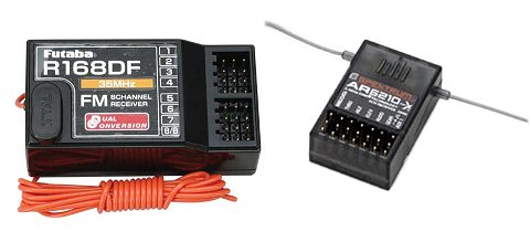
Above: a MHz Rx, left, and a 2.4GHz one, right.
The receiver is located inside the model and is connected to each servo (and electronic speed control - ESC - in electric planes), by servo leads. A thin wire antenna extends from within the Rx's printed circuit board (PCB).
A primary feature of the Rx are the connection slots; each slot consists of three metal pins onto which a servo lead connects (3 pins - positive, negative & signal).
There is one receiver slot per channel, so a 4-channel plane would require 4 slots (in fact 5 for an IC powered plane, because of the additional receiver battery pack).
As with the Tx, a MHz receiver antenna is 3' to 4' long compared to a 2.4GHz Rx antenna which might only be an inch or so in length.
A MHz receiver antenna must be secured along the plane's fuselage and should never be cut or looped up to reduce its length. By doing so, the ability of the Rx to receive the Tx signal is drastically reduced and this usually has disastrous consequences. The plane will very quickly fly out of radio range, and you'll lose complete control. Once that happens a crash or a lost airplane is inevitable!
In the same way as a traditional TV / radio receives signals from a broadcasting station, so a radio control Rx receives the signals emitted by the transmitter. These signals are then passed through to the servos, or ESC, which respond appropriately.
RC Servos
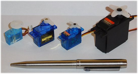
Above: servos come in various sizes, weights and strengths.
As mentioned, the number of servos in a radio controlled model varies according to the number of channels that the radio control gear has and the aircraft requires.
A servo consists of a PCB (amplifier), electric motor, feedback potentiometer and a set of either nylon or metal gears (or mixed) that may or may not be ball-raced. The servo casing will be plastic or aluminium.
An output shaft is an integral part of the gearing and exits through the top of the servo; the servo arm is connected to the shaft and is held in place by a small screw.
The servo arm is directly connected to the respective control surface by some kind of control linkage (a rigid metal wire rod or Bowden cable, for example), so any movement of the arm results in direct movement of that surface, be it the ailerons, elevator, rudder or whatever.
RC servo operation is all about electrical pulse modulation and voltage error correction within the potentiometer. You can read more about this on the rc servo page.
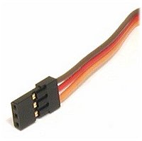 Servos leads typically have three (sometimes 4) fine-gauge wires that connect to the receiver slot pins - a positive, negative and signal wire. The wires are generally colour coded according to manufacturer.
The wires terminate in a plastic connector, the 'flat blade' type (shown right is the Spektrum/JR type) being the most common, which is pushed into the appropriate channel slot of the receiver.
RC servos come in various sizes and strengths, from tiny 'feather-weight' ones to giant 1/4 scale ones (so called because they're commonly used in 1/4 scale aircraft). 'Micro' and 'Nano' servos have become increasingly common in recent years as rc aircraft have become smaller and smaller, and the technology to produce them has advanced.
Digital servos are increasingly common, although analogue ones are still widely used. Digi servos offer faster response times (lower latency) and more holding power i.e the strength to hold a large control surface against the airflow, without failing.
Servo strength is measured in terms of torque, expressed in Oz.in (ounce-inches) or in kg.cm (kilogram-centimeters) depending on where you are in the world. Either way, the torque rating states how much force the servo can exert at a given distance out from the central output shaft. For example, a 1.6kg.cm servo can exert 1.6kg at 1cm from the shaft. The further out from the shaft you go, the weaker the torque is and for double the distance, so the force halves. Conversely, if the distance is halved then the torque doubles.
Another servo rating you'll see is servo speed and this lets you know how fast a servo shaft takes to rotate through 60°, usually given in hundredths of one second.
Tx & Rx Crystals
 Crystals are used in MHz rc systems and determine which frequency channel the radio control gear will operate on.
In North America, for example, rc aircraft have a designated set number of channels that fall in to the 72MHz frequency band, ranging from 72.010MHz to 72.990MHz. There are 50 different channels in all, spread at 20kHz intervals.
2.4GHz rc systems don't require crystals due to the different technology used.
Both the Tx and Rx need their own crystal to operate, both on identical frequency channels. The crystal typically contains quartz and works because of the piezoelectric effect - when an electric current flows through the quartz, it naturally resonates at a particular frequency. This resonance can be manipulated to determine which frequency is utilised.
As 2.4GHz radio control gear becomes the norm, rc crystals will doubtless become obsolete in the not-too-distant future.
Radio Control Gear Cells & Batteries
 While certain rc systems can use disposable (alkaline) cells, it's a better idea to use rechargeable ones wherever possible. Although the initial cost is more, this is soon recouped because rechargeable cells have a very long life of around 1000 charges. Much cheaper in the long term!
Nickel Cadmium (NiCD or nicad) rechargeable cells were traditionally used in radio control gear but Nickel Metal Hydride (NiMH) cells with much higher capacities and better performance have all but made nicads extinct within the hobby.
More recently lithium polymer ion (Li-Po or lipoly) and lithium iron phosphate (LiFe) Tx and Rx packs offer even greater performance and are now taking the place of NiMH cells and packs. The lithium-based battery packs give excellent performance.
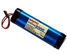
Traditionally, a MHz transmitter would take an 8-cell pack and the receiver and servos would get their power from a 4-cell pack inside the plane. But with the development of mainstream electric power, receivers and servos in EP models get power directly from the lithium flight pack via a BEC, or battery eliminator circuit.
The BEC is integrated into the electronic speed control and regulates a steady 5 volts (or so) from the flight pack to power the receiver and servos. Hence a separate receiver battery pack isn't required, as it is in an IC powered plane.
If a Tx does require 8 NiMH cells, it's best to use a soldered and sealed pack, rather than individual cells. In such a pack, the cells are soldered together in series and just a single connector connects to the Tx. This greatly reduces the risk of poor cell-to-terminal connection, which would invariably result in your plane going out of control.
The radio control gear battery level is of paramount importance when it comes to rc flying - if even just one of the cells has a low voltage then you will not have control over your plane for very long, since a reduced voltage results in a weaker radio signal and hence a reduced radio range.
Choosing the right Radio Control Gear
The choice of rc gear these days is huge and it's easy to become overwhelmed, but choosing a suitable radio needn't be difficult if you think it through and do your research.
Your budget is going to determine much of the answer, but there are other important things to consider too. Here are a few pointers to bear in mind...
- MHz or GHz - without doubt 2.4GHz! MHz radios, although still used, are on their way out.
- Number of channels - you'll be hard pushed to find a new radio with less than 6 channels these days, but how many you need depends on how seriously you want to take the hobby. If you're quickly going to get in deep with more complex models, then you would soon outgrow a 6-channel radio, so an 8+ channel one might suit you better.
- Features & functions - modern computer radios already do way more than the beginner needs but, again, if you see yourself getting seriously in to rc flying then you'll be needing at least a mid-range radio, not a basic bottom end one. Essentially, the more complex the plane you want to fly, the more complex the radio needs to be.
- Comfort - easily overlooked, but if you're not happy holding the Tx then your enjoyment of using it will be dampened. If you can get to a local hobby shop, try out a few radios and see how they feel.
- Reputation - by this I mean reputation and reliability of the brand. Steer clear of the Far Eastern radios going cheap on eBay that nobody has ever heard of, and go with a mainstream brand - there are plenty to choose from these days. Top brands include Spektrum, Futaba, JR, HiTech, Graupner, Multiplex, FRSky to name a few.
- New or used - if you can, buy new. Buying used radio control gear carries a risk; you don't know its history, how badly it's been treated or even if it's stolen goods! If you really do need to buy second-hand, try and buy from someone you know who has treated it well.
- Which Tx mode - this is more than likely going to be determined for you, but if in doubt opt for Mode 2 because it's by far the most widely used.
Well hopefully this article has given you an insight in to how your radio control gear does what it does. As I said at the start of the page, take the time to understand your rc system and you'll get a much more rewarding experience - don't just 'waggle the sticks' without knowing what's going on behind the scenes!
More Detail in my E-book
 This whole radio control gear topic is covered in much more detail in my e-book The Beginner's Guide To Flying RC Airplanes, along with everything else you need to know about getting started in this exhilarating and somewhat addictive hobby!
The e-book answers all the questions that you're likely to ask, and takes you step-by-step all the way to get you flying an rc airplane quickly and safely.
You can see the Beginner's Guide here.
You might also like to read about...


All of this and much more is covered in our Beginner’s Guide 👇
The Beginner’s Guide To Flying RC Airplanes is a 139-page, easy-to-read e-book written for complete newcomers. It explains exactly what to buy, where to fly, and how to avoid costly mistakes.
📖 Start reading now